Camera Calibration
Note
We assume that by now you have already read the previous tutorials. If not, please check previous tutorials at http://opencv-java-tutorials.readthedocs.org/en/latest/index.html. You can also find the source code and resources at https://github.com/opencv-java/
우리는 지금까지 이미 이전 튜토리얼을 읽었다 고 가정합니다. 그렇지 않은 경우 http://opencv-java-tutorials.readthedocs.org/en/latest/index.html에서 이전 자습서를 확인하십시오. https://github.com/opencv-java/에서 소스 코드와 리소스를 찾을 수도 있습니다.
Warning
This tutorial is not updated to OpenCV 3.0.
이 자습서는 OpenCV 3.0으로 업데이트되지 않습니다.
Goal
The goal of this tutorial is to learn how to calibrate a camera given a set of chessboard images.
이 튜토리얼의 목적은 일련의 체스 보드 이미지를 사용하여 카메라를 보정하는 방법을 배우는 것입니다.
What is the camera calibration?
The camera calibration is the process with which we can obtain the camera parameters such as intrinsic and extrinsic parameters, distortions and so on. The calibration of the camera is often necessary when the alignment between the lens and the optic sensors chip is not correct; the effect produced by this wrong alignment is usually more visible in low quality cameras.
카메라 보정은 내재적 및 외적 매개 변수, 왜곡 등과 같은 카메라 매개 변수를 얻을 수있는 프로세스입니다. 카메라 보정은 렌즈와 광 센서 칩 사이의 정렬이 올바르지 않은 경우에 종종 필요합니다. 이 잘못된 정렬로 인해 생성되는 효과는 일반적으로 저품질 카메라에서 더 잘 보입니다.
Calibration Pattern
As we said earlier we are going to need some sort of pattern that the program can recognize in order to make the calibration work. The pattern that we are going to use is a chessboard image.
앞에서 말했듯이, 우리는 보정 작업을하기 위해 프로그램이 인식 할 수있는 패턴을 필요로 할 것입니다. 우리가 사용할 패턴은 체스 판 이미지입니다.
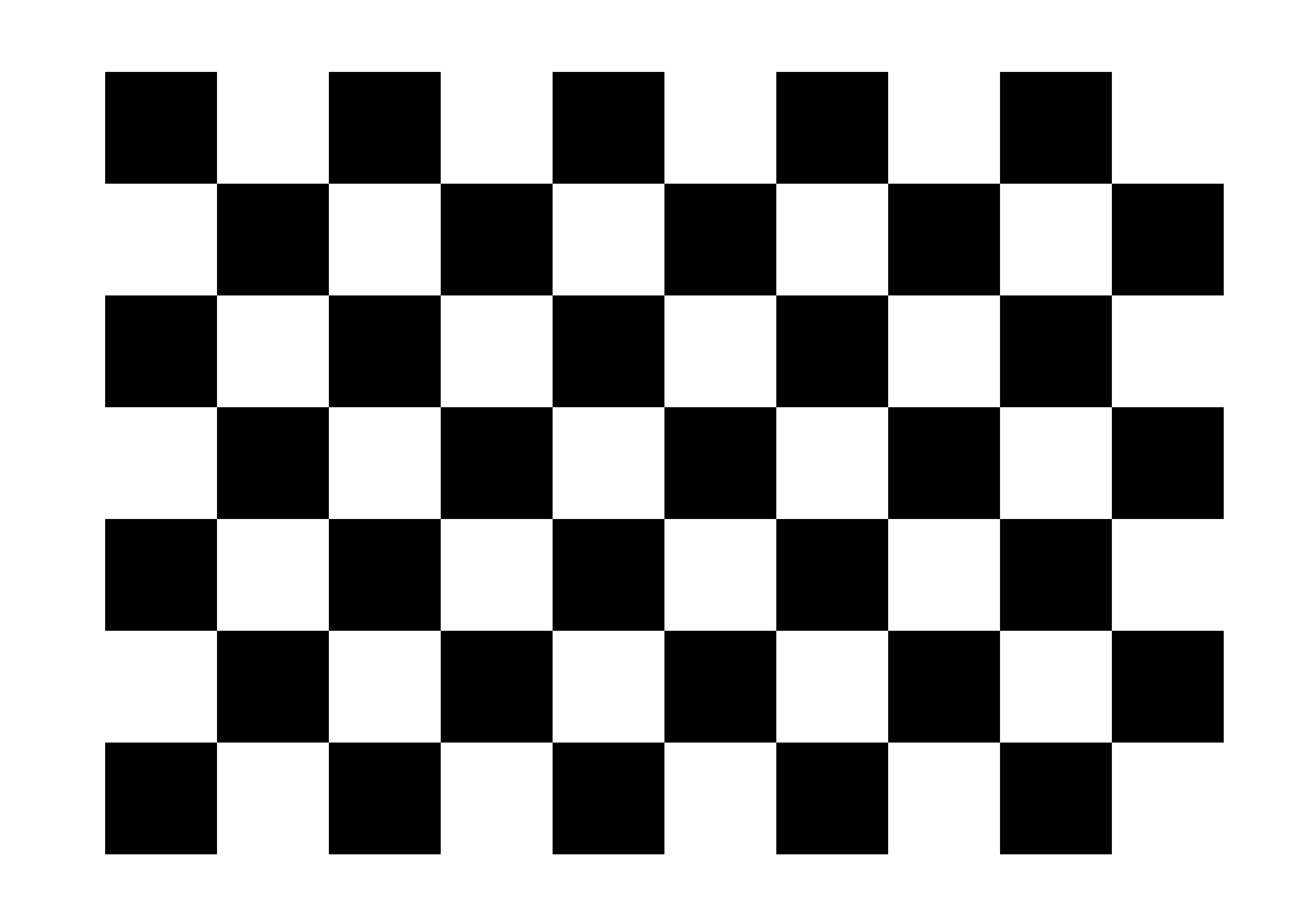
The reason why we use this image is because there are some OpenCV functions that can recognize this pattern and draw a scheme which highlights the intersections between each block. To make the calibration work you need to print the chessboard image and show it to the cam; it is important to maintain the sheet still, better if stick to a surface. In order to make a good calibration, we need to have about 20 samples of the pattern taken from different angles and distances.
이 이미지를 사용하는 이유는 이 패턴을 인식 할 수있는 OpenCV 함수가 있고 각 블록 간의 교차를 강조하는 체계를 그리기 때문입니다. 보정 작업을하려면 체스 판 이미지를 인쇄하여 캠에 표시해야합니다. 표면에 달라 붙으면 시트를 더 잘 유지하는 것이 중요합니다. 좋은 교정을하기 위해서, 우리는 서로 다른 각도와 거리에서 찍은 패턴의 약 20 샘플을 가질 필요가 있습니다.
What we will do in this tutorial
- In this guide, we will:
- Create some TextEdit field to give some inputs to our program
- Recognize the pattern using some OpenCV functions
- Calibrate and show the video stream.
Getting Started
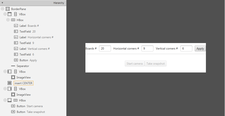
Create a new JavaFX project (e.g. “CameraCalibration”) with the usual OpenCV user library. Open Scene Builder and add a Border Pane with:
일반적인 OpenCV 사용자 라이브러리를 사용하여 새로운 JavaFX 프로젝트 (예 : "CameraCalibration")를 만듭니다. Scene Builder를 열고 다음과 함께 테두리 창을 추가하십시오.
- on TOP we need to have the possibility to set the number of samples for the calibration, the number of horizontal corners we have in the test image, the number of vertical corners we have in the test image and a button to update this data. To make things cleaner let’s put all these elements inside a HBox.
TOP에는 보정을위한 샘플 수, 테스트 이미지에 포함 된 수평 모서리 수, 테스트 이미지에 포함 된 수직 모퉁이 수 및이 데이터를 업데이트하는 버튼을 설정할 수있는 기능이 필요합니다. 모든 것을 깨끗하게 만들려면이 모든 요소들을 HBox 안에 넣자.
<HBox alignment="CENTER" spacing="10">
Let’s also add some labels before each text fields. Each text field is going to need an id, and let’s put a standard value for them already.
각 텍스트 필드 앞에 레이블을 추가해 보겠습니다. 각 텍스트 필드에는 ID가 필요하며 이미 표준 값을 입력 해 두었습니다.
<Label text="Boards #" />
<TextField fx:id="numBoards" text="20" maxWidth="50" />
<Label text="Horizontal corners #" />
<TextField fx:id="numHorCorners" text="9" maxWidth="50" />
<Label text="Vertical corners #" />
<TextField fx:id="numVertCorners" text="6" maxWidth="50" />
For the button instead, set the id and a method for the onAction field:
버튼 대신에 onAction 필드의 id와 메소드를 설정하십시오 :
<Button fx:id="applyButton" alignment="center" text="Apply" onAction="#updateSettings" />
- on the LEFT add an ImageView inside a VBox for the normal cam stream; set an id for it.
LEFT에서 ImageView를 일반적인 캠 스트림 용 VBox에 추가합니다. 그것을위한 id를 설정하십시오.
<ImageView fx:id="originalFrame" />
- on the RIGHT add an ImageView inside a VBox for the calibrated cam stream; set an id for it.
오른쪽에 조정 된 캠 스트림에 대한 VBox 내부에 ImageView를 추가합니다. 그것을위한 id를 설정하십시오.
<ImageView fx:id="originalFrame" />
- in the BOTTOM add a start/stop cam stream button and a snapshot button inside a HBox; set an id and a action method for each one.
하단에는 HBox 내부에 시작 / 정지 캠 스트림 버튼과 스냅 샷 버튼이 추가됩니다. 각각에 대해 id와 action 메소드를 설정하십시오.
<Button fx:id="cameraButton" alignment="center" text="Start camera" onAction="#startCamera" disable="true" />
<Button fx:id="snapshotButton" alignment="center" text="Take snapshot" onAction="#takeSnapshot" disable="true" />
Your GUI will look something like this:
GUI는 다음과 같이 보입니다.
Pattern Recognition
The calibration process consists on showing to the cam the chessboard pattern from different angles, depth and points of view. For each recognized pattern we need to track:
some reference system’s 3D point where the chessboard is located (let’s assume that the Z axe is always 0):
체스 판이있는 참조 시스템의 3D 점 (Z 축은 항상 0이라고 가정) :for (int j = 0; j < numSquares; j++) obj.push_back(new MatOfPoint3f(new Point3(j / this.numCornersHor, j % this.numCornersVer, 0.0f)));the image’s 2D points (operation made by OpenCV with findChessboardCorners):
이미지의 2D 점 (OpenCV에서 findChessboardCorners로 작업) :boolean found = Calib3d.findChessboardCorners(grayImage, boardSize, imageCorners, Calib3d.CALIB_CB_ADAPTIVE_THRESH + Calib3d.CALIB_CB_NORMALIZE_IMAGE + Calib3d.CALIB_CB_FAST_CHECK);
The findChessboardCorners function attempts to determine whether the input image is a view of the chessboard pattern and locate the internal chessboard corners. Its parameters are:
findChessboardCorners 함수는 입력 이미지가 체스 판 패턴의 뷰인지 내부 체스 보드 모서리인지를 확인하려고 시도합니다. 그 매개 변수는 다음과 같습니다.
- image Source chessboard view. It must be an 8-bit grayscale or color image.
- patternSize Number of inner corners per a chessboard row and column
- corners Output array of detected corners.
이미지 소스 체스 판보기. 8 비트 그레이 스케일 또는 컬러 이미지 여야합니다.patternSize 체스 판 행과 열당 내부 모서리 수corners 감지 된 모서리의 출력 배열입니다.
- flags Various operation flags that can be zero or a combination of the following values:
CV_CALIB_CB_ADAPTIVE_THRESHUse adaptive thresholding to convert the image to black and white, rather than a fixed threshold level (computed from the average image brightness).CV_CALIB_CB_NORMALIZE_IMAGENormalize the image gamma with “equalizeHist” before applying fixed or adaptive thresholding.CV_CALIB_CB_FILTER_QUADSUse additional criteria (like contour area, perimeter, square-like shape) to filter out false quads extracted at the contour retrieval stage.CALIB_CB_FAST_CHECKRun a fast check on the image that looks for chessboard corners, and shortcut the call if none is found. This can drastically speed up the call in the degenerate condition when no chessboard is observed.flags 0 또는 다음 값의 조합 일 수있는 다양한 조작 플래그 :- CV_CALIB_CB_ADAPTIVE_THRESH 적응 형 임계 값을 사용하여 고정 된 임계 값 레벨 (평균 이미지 밝기에서 계산 됨) 대신 이미지를 흑백으로 변환합니다.- CV_CALIB_CB_NORMALIZE_IMAGE 고정 된 또는 적응 형 임계 값을 적용하기 전에 "equalizeHist"로 이미지 감마를 표준화합니다.- CV_CALIB_CB_FILTER_QUADS 등고선 검색 단계에서 추출 된 잘못된 사각형을 필터링하려면 추가 기준 (윤곽선 영역, 둘레, 사각형 모양과 같은)을 사용합니다.- CALIB_CB_FAST_CHECK 체스 보드 모서리를 찾는 이미지를 빠르게 검사하고 아무 것도 발견되지 않으면 바로 가기를 실행합니다. 이것은 체스 판이 관찰되지 않는 퇴보 상태에서 통화 속도를 크게 높일 수 있습니다.
Warning
Before doing the findChessboardCorners convert the image to grayscale and save the board size into a Size variable:
findChessboardCorners를 수행하기 전에 이미지를 회색 음영으로 변환하고 보드 크기를 Size 변수에 저장합니다.
Imgproc.cvtColor(frame, grayImage, Imgproc.COLOR_BGR2GRAY);
Size boardSize = new Size(this.numCornersHor, this.numCornersVer);
If the recognition went well found should be true.
인정이 잘 된 경우 사실이어야합니다.
For square images the positions of the corners are only approximate. We may improve this by calling the cornerSubPix function. It will produce better calibration result.
사각형 이미지의 경우 모서리의 위치는 대략적인 것입니다. cornerSubPix 함수를 호출하여이를 개선 할 수 있습니다. 더 나은 교정 결과를 얻을 수 있습니다.
TermCriteria term = new TermCriteria(TermCriteria.EPS | TermCriteria.MAX_ITER, 30, 0.1);
Imgproc.cornerSubPix(grayImage, imageCorners, new Size(11, 11), new Size(-1, -1), term);
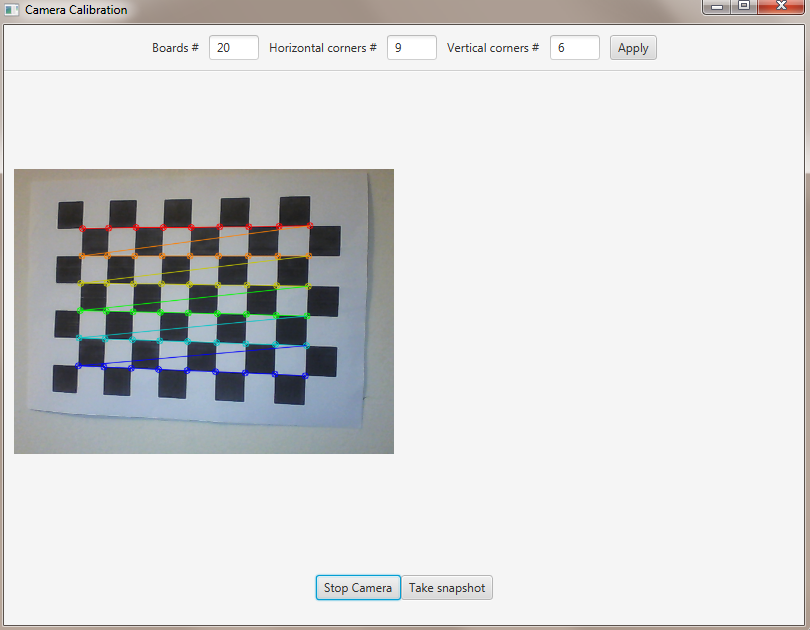
We can now highlight the found points on stream:
이제 스트림에서 찾은 점을 강조 표시 할 수 있습니다.
Calib3d.drawChessboardCorners(frame, boardSize, imageCorners, found);
The function draws individual chessboard corners detected either as red circles if the board was not found, or as colored corners connected with lines if the board was found.
이 함수는 보드가 발견되지 않으면 빨간색 원으로 감지 된 개별 체스 보드 모서리 또는 보드가 발견되면 선으로 연결된 컬러 모서리를 그립니다.
Its parameters are:
그 매개 변수는 다음과 같습니다.
- image Destination image. It must be an 8-bit color image.
- patternSize Number of inner corners per a chessboard row and column.
- corners Array of detected corners, the output of findChessboardCorners.
- patternWasFound Parameter indicating whether the complete board was found or not. The return value of
findChessboardCornersshould be passed here.이미지 대상 이미지. 8 비트 컬러 이미지 여야합니다.patternSize 체스 판 행과 열당 내부 모서리 수입니다.corners 감지 된 모서리의 배열, findChessboardCorners의 출력입니다.patternWasFound 전체 보드를 찾았는지 여부를 나타내는 매개 변수입니다. findChessboardCorners의 반환 값은 여기에 전달되어야합니다.
Now we can activate the Snapshot button to save the data.
이제 스냅 샷 버튼을 활성화하여 데이터를 저장할 수 있습니다.
this.snapshotButton.setDisable(false);
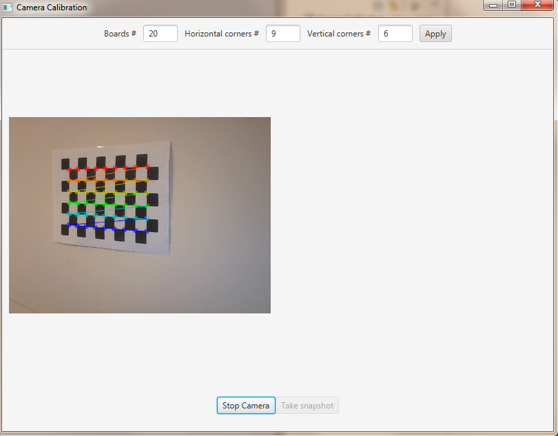
We should take the set number of “snapshots” from different angles and depth, in order to make the calibration.
캘리브레이션을하기 위해 설정 한 수의 "스냅 샷"을 다른 각도와 깊이에서 가져와야합니다.
Note
We don’t actually save the image but just the data we need.
우리는 실제로 이미지를 저장하는 것이 아니라 필요한 데이터 만 저장합니다.
Saving Data
By clicking on the snapshot button we call the takeSnapshot method. Here we need to save the data (2D and 3D points) if we did not make enough sample:
스냅 샷 버튼을 클릭하면 takeSnapshot 메서드가 호출됩니다. 충분한 샘플을 만들지 않으면 데이터 (2D 및 3D 포인트)를 저장해야합니다.
this.imagePoints.add(imageCorners);
this.objectPoints.add(obj);
this.successes++;
Otherwise we can calibrate the camera.
그렇지 않으면 우리는 카메라를 보정 할 수 있습니다.
Camera Calibration
For the camera calibration we should create initiate some needed variable and then call the actual calibration function:
카메라 보정을 위해 필요한 변수를 시작한 다음 실제 보정 함수를 호출해야합니다.
List<Mat> rvecs = new ArrayList<>();
List<Mat> tvecs = new ArrayList<>();
intrinsic.put(0, 0, 1);
intrinsic.put(1, 1, 1);

Calib3d.calibrateCamera(objectPoints, imagePoints, savedImage.size(), intrinsic, distCoeffs, rvecs, tvecs);
The calibrateCamera function estimates the intrinsic camera parameters and extrinsic parameters for each of the views. The algorithm is based on [Zhang2000] and [BouguetMCT]. The coordinates of 3D object points and their corresponding 2D projections in each view must be specified. Its parameters are:
calibrateCamera 함수는 각 뷰에 대한 내장 카메라 매개 변수와 외부 매개 변수를 예측합니다. 이 알고리즘은 [Zhang2000]과 [BouguetMCT]를 기반으로합니다. 각 뷰의 3D 객체 점 및 해당 2D 투영 좌표를 지정해야합니다. 그 매개 변수는 다음과 같습니다.
- objectPoints In the new interface it is a vector of vectors of calibration pattern points in the calibration pattern coordinate space. The outer vector contains as many elements as the number of the pattern views. The points are 3D, but since they are in a pattern coordinate system, then, if the rig is planar, it may make sense to put the model to a XY coordinate plane so that Z-coordinate of each input object point is 0.
- imagePoints It is a vector of vectors of the projections of calibration pattern points.
- imageSize Size of the image used only to initialize the intrinsic camera matrix.
- cameraMatrix Output 3x3 floating-point camera matrix A = |fx 0 cx| |0 fy cy| |0 0 1|. If
CV_CALIB_USE_INTRINSIC_GUESSand/orCV_CALIB_FIX_ASPECT_RATIOare specified, some or all of fx, fy, cx, cy must be initialized before calling the function.- distCoeffs Output vector of distortion coefficients of 4, 5, or 8 elements.
- rvecs Output vector of rotation vectors estimated for each pattern view. That is, each k-th rotation vector together with the corresponding k-th translation vector.
- tvecs Output vector of translation vectors estimated for each pattern view.
objectPoints 새로운 인터페이스에서 이것은 교정 패턴 좌표 공간에서 교정 패턴 포인트의 벡터 벡터입니다. 외부 벡터는 패턴 뷰의 수만큼 요소를 포함합니다. 점은 3D이지만 패턴 좌표계에 있기 때문에 리깅이 평면 인 경우 각 입력 객체 점의 Z 좌표가 0이되도록 모형을 XY 좌표 평면에 배치하는 것이 좋습니다.imagePoints 이것은 교정 패턴 포인트의 투영 벡터의 벡터입니다.imageSize 내장 카메라 매트릭스를 초기화하는 데에만 사용되는 이미지의 크기입니다.cameraMatrix 출력 3x3 부동 소수점 카메라 매트릭스 A = | fx 0 cx | | 0 fy cy | | 0 0 1 |. CV_CALIB_USE_INTRINSIC_GUESS 및 / 또는 CV_CALIB_FIX_ASPECT_RATIO가 지정되면, 함수를 호출하기 전에 fx, fy, cx, cy의 일부 또는 전부를 초기화해야합니다.distCoeffs 4, 5 또는 8 요소의 왜곡 계수 출력 벡터입니다.rvecs 각 패턴보기에 대해 추정 된 회전 벡터의 출력 벡터입니다. 즉, 각 k 번째 회전 벡터는 해당 k 번째 번역 벡터와 함께 나타납니다.tvecs 각 패턴보기에 대해 추정 된 변환 벡터의 출력 벡터입니다.
We ran calibration and got camera’s matrix with the distortion coefficients we may want to correct the image using undistort function:
우리는 캘리브레이션을 실행하고 왜곡 계수를 가진 카메라의 행렬을 얻었습니다. 왜곡 계수를 사용하여 이미지를 수정할 수 있습니다.
if (this.isCalibrated)
{
    // prepare the undistored image
    Mat undistored = new Mat();
    Imgproc.undistort(frame, undistored, intrinsic, distCoeffs);
    undistoredImage = mat2Image(undistored);
}
The undistort function transforms an image to compensate radial and tangential lens distortion.
왜곡 방지 기능은 방사형 및 접선 렌즈 왜곡을 보정하기 위해 이미지를 변환합니다.
The source code of the entire tutorial is available on GitHub.
'DEV' 카테고리의 다른 글
| [ORACLE] MERGE INTO SEMPLE (0) | 2018.01.02 |
|---|---|
| 정렬 알고리즘 시각화 JAVA 소스 (0) | 2017.12.14 |
| 8. Object Detection (객체 감지) (0) | 2017.12.10 |
| 7. Image Segmentation (이미지 분할) (0) | 2017.12.10 |
| 6. Face Detection and Tracking (얼굴 인식 및 추적) (0) | 2017.12.09 |
