OpenCV Basics
Note
We assume that by now you have already read the previous tutorials. If not, please check previous tutorials at http://opencv-java-tutorials.readthedocs.org/en/latest/index.html. You can also find the source code and resources at https://github.com/opencv-java/
우리는 지금까지 이미 이전 튜토리얼을 읽었다 고 가정합니다. 그렇지 않은 경우 http://opencv-java-tutorials.readthedocs.org/en/latest/index.html에서 이전 자습서를 확인하십시오. https://github.com/opencv-java/에서 소스 코드와 리소스를 찾을 수도 있습니다.
Note
We assume that by now you have already read the previous tutorials. If not, please check previous tutorials at http://opencv-java-tutorials.readthedocs.org/en/latest/index.html. You can also find the source code and resources at https://github.com/opencv-java/
What we will do in this tutorial
- In this guide, we will:
- Create a basic checkbox interaction to alter the color of the video stream.
- Add a basic checkbox interaction to “alpha over” a logo to the video stream.
- Display the video stream histogram (both one and three channels).
이 가이드에서 우리는 :기본 체크 박스 상호 작용을 만들어 비디오 스트림의 색상을 변경합니다.로고를 "알파 오버"하는 기본 체크 박스 상호 작용을 비디오 스트림에 추가하십시오.비디오 스트림 히스토그램 (하나 및 세 채널 모두)을 표시합니다.
- In this guide, we will:
- Create a basic checkbox interaction to alter the color of the video stream.
- Add a basic checkbox interaction to “alpha over” a logo to the video stream.
- Display the video stream histogram (both one and three channels).
Getting started
For this tutorial we can create a new JavaFX project and build a scene as the one realized in the previous one. So we’ve got a window with a border pane in which:
이 튜토리얼에서는 새로운 JavaFX 프로젝트를 만들고 이전에 실현 한 장면을 만들 수 있습니다. 그래서 경계 창이있는 창이 있습니다.- in the BOTTOM we have a button inside a HBox:
바닥에는 HBox 내부에 버튼이 있습니다.<HBox alignment="CENTER" >
<padding>
<Insets top="25" right="25" bottom="25" left="25"/>
</padding>
<Button fx:id="button" alignment="center" text="Start camera" onAction="#startCamera" />
</HBox>
- in the CENTER we have a ImageView:
CENTER에는 ImageView가 있습니다.<ImageView fx:id="currentFrame" />
For this tutorial we can create a new JavaFX project and build a scene as the one realized in the previous one. So we’ve got a window with a border pane in which:
- in the BOTTOM we have a button inside a HBox:
<HBox alignment="CENTER" >
   <padding>
      <Insets top="25" right="25" bottom="25" left="25"/>
   </padding>
   <Button fx:id="button" alignment="center" text="Start camera" onAction="#startCamera" />
</HBox>
- in the CENTER we have a ImageView:
<ImageView fx:id="currentFrame" />
Color channel checkbox
Let’s open our fxml file with Scene Builder and add to the RIGHT field of our BorderPane a vertical box VBox. A VBox lays out its children in a single vertical column. If the VBox has a border and/or padding set, then the contents will be layed out within those insets. Also it will resize children (if resizable) to their preferred heights and uses its fillWidth property to determine whether to resize their widths to fill its own width or keep their widths to their preferred (fillWidth defaults to true). A HBox works just like a VBox but it lays out its children horizontally instead of vertically.
장면 빌더를 사용하여 fxml 파일을 열고 BorderPane의 오른쪽 필드에 수직 상자 VBox를 추가합시다. VBox는 자녀를 하나의 세로 열에 배치합니다. VBox에 보더 및 / 또는 패딩 세트가있는 경우, 그 인 세트 내의 내용이 레이아웃됩니다. 또한 자식 (크기 재조정 할 수있는 경우)의 크기를 원하는 높이로 조정하고 fillWidth 속성을 사용하여 너비를 채우기 위해 너비를 조정하거나 너비를 원하는대로 유지할지 결정합니다 (fillWidth의 기본값은 true). HBox는 VBox와 똑같이 작동하지만 수직으로가 아니라 수평으로 자식을 배치합니다.Now we can put inside the VBox a new checkbox, change its text to “Show in gray scale”, and set an id (e.g., “grayscale”).
이제 VBox 내부에 새로운 체크 박스를 삽입하고 텍스트를 "그레이 스케일로 표시"로 변경하고 ID (예 : "회색 음영")를 설정할 수 있습니다.<CheckBox fx:id="grayscale" text="Show in gray scale" />
Let’s also add a title to this section by putting a text before our new checkbox, but still inside the VBox. Then, set its text to “Controls” (we can find the text element under the Shapes menu).
새로운 체크 박스 앞에 텍스트를 놓음으로써이 섹션에 제목을 추가하되, 여전히 VBox 안에 넣으십시오. 그런 다음 텍스트를 "컨트롤"로 설정하십시오 (우리는 도형 메뉴에서 텍스트 요소를 찾을 수 있습니다).<Text text="Controls" />
In the Scene Builder we now have:
Scene Builder에서 우리는 이제 다음을 얻습니다 :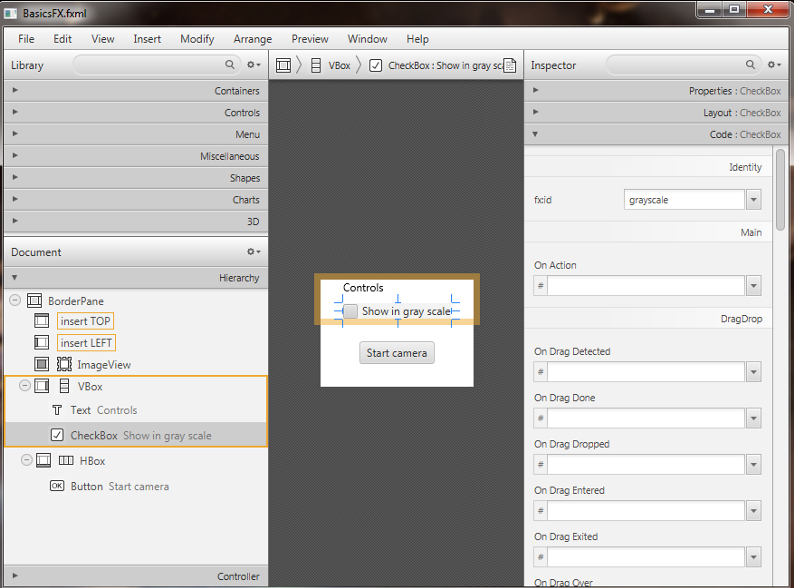
The graphic interface is complete for the first task, now we need to work on the controller; in the previous tutorial we could control the number of channels displayed on screen with the line:
첫 번째 작업을 위해 그래픽 인터페이스가 완성되었으므로 이제 컨트롤러에 대해 작업해야합니다. 이전 튜토리얼에서 우리는 화면에 표시되는 채널 수를 다음 줄과 함께 제어 할 수있었습니다.Imgproc.cvtColor(frame, frame, Imgproc.COLOR_BGR2GRAY);
In order to control this conversion with the check box, we have to link the check box with a FXML variable:
확인란을 사용하여이 변환을 제어하려면 확인란을 FXML 변수와 연결해야합니다.@FXML
private CheckBox grayscale;
Now we can implement the control by adding a simple “if” condition which will perform the conversion only if our check box is checked:
이제 우리는 확인란을 선택했을 때만 변환을 수행하는 간단한 "if"조건을 추가하여 컨트롤을 구현할 수 있습니다.if (grayscale.isSelected())
{
Imgproc.cvtColor(frame, frame, Imgproc.COLOR_BGR2GRAY);
}
Let’s open our fxml file with Scene Builder and add to the RIGHT field of our BorderPane a vertical box VBox. A VBox lays out its children in a single vertical column. If the VBox has a border and/or padding set, then the contents will be layed out within those insets. Also it will resize children (if resizable) to their preferred heights and uses its fillWidth property to determine whether to resize their widths to fill its own width or keep their widths to their preferred (fillWidth defaults to true). A HBox works just like a VBox but it lays out its children horizontally instead of vertically.
Now we can put inside the VBox a new checkbox, change its text to “Show in gray scale”, and set an id (e.g., “grayscale”).
<CheckBox fx:id="grayscale" text="Show in gray scale" />
Let’s also add a title to this section by putting a text before our new checkbox, but still inside the VBox. Then, set its text to “Controls” (we can find the text element under the Shapes menu).
<Text text="Controls" />
In the Scene Builder we now have:
The graphic interface is complete for the first task, now we need to work on the controller; in the previous tutorial we could control the number of channels displayed on screen with the line:
Imgproc.cvtColor(frame, frame, Imgproc.COLOR_BGR2GRAY);
In order to control this conversion with the check box, we have to link the check box with a FXML variable:
@FXML
private CheckBox grayscale;
Now we can implement the control by adding a simple “if” condition which will perform the conversion only if our check box is checked:
if (grayscale.isSelected())
{
   Imgproc.cvtColor(frame, frame, Imgproc.COLOR_BGR2GRAY);
}
Load an Image and Add it to the Stream
The next step is to add another check box which, if checked, will trigger the display of an image over the camera stream. Let’s start by adding the image to the project; create a new folder in the root directory of your project and put the image in there. In my project I have a resources folder with a Poli.png image. Go back to Eclipse and refresh your project (you should have the new folder in it). Let’s open the FXML file with Scene Builder and add a new checkbox below the one that controls the stream colors; we have to set the text, the name of the method in the OnAction field and an id. In the code we will have for example:
다음 단계는 다른 체크 박스를 추가하는 것입니다.이 확인란을 선택하면 카메라 스트림을 통해 이미지가 표시됩니다. 프로젝트에 이미지를 추가하는 것으로 시작해 보겠습니다. 프로젝트의 루트 디렉토리에 새 폴더를 만들고 거기에 이미지를 넣으십시오. 내 프로젝트에는 Poli.png 이미지가있는 resources 폴더가 있습니다. Eclipse로 돌아가서 프로젝트를 새로 고침하십시오 (새 폴더가 있어야 함). 장면 빌더로 FXML 파일을 열고 스트림 색상을 제어하는 아래에 새로운 체크 상자를 추가하십시오. 우리는 텍스트, OnAction 필드에있는 메소드의 이름과 ID를 설정해야합니다. 코드에서 우리는 예를 들어 :<CheckBox fx:id="logoCheckBox" text="Show logo" onAction="#loadLogo" />
In the controller file we have to define a new variable associated with the checkbox, the method set on the OnAction field and adapt the code so that it will display the logo when the checkbox is checked and the stream is on. Variable:
컨트롤러 파일에서 우리는 체크 박스와 연결된 새로운 변수와 OnAction 필드에 설정된 메소드를 정의하고 체크 박스가 선택되고 스트림이 켜져있을 때 로고를 표시하도록 코드를 수정해야합니다. 변하기 쉬운:@FXML
private CheckBox logoCheckBox;
loadLogo method: In this method we are going to load the image whenever the logoCheckBox id selected (checked). In order to load the image we have to use a basic OpenCV function: imread. It returns a Mat and takes the path of the image and a flag (> 0 RGB image, =0 grayscale, <0 with the alpha channel).
loadLogo 메소드 :이 메소드에서는 logoCheckBox id가 선택 (선택) 될 때마다 이미지를로드합니다. 이미지를 로드하려면 기본 OpenCV 함수 imread를 사용해야합니다. Mat를 반환하고 이미지의 경로와 플래그 (> 0 RGB 이미지, = 0 회색 음영, 알파 채널이있는 <0)를 사용합니다.@FXML
protected void loadLogo()
{
if (logoCheckBox.isSelected())
this.logo = Imgcodecs.imread("resources/Poli.png");
}
Adapt the code.
We are going to add some variants to the code in order to display our logo in a specific region of the stream. This means that for each frame capture, before the image could be converted into 1 or 3 channels, we have to set a ROI (region of interest) in which we want to place the logo. Usually a ROI of an image is a portion of it, we can define the ROI as a Rect object. Rect is a template class for 2D rectangles, described by the following parameters:
스트림의 특정 영역에 로고를 표시하기 위해 코드에 몇 가지 변형을 추가 할 것입니다. 즉, 각 프레임 캡처에 대해 이미지를 1 또는 3 채널로 변환 할 수 있기 전에 로고를 배치 할 ROI (관심 영역)를 설정해야합니다. 일반적으로 이미지의 ROI는 일부이므로 ROI를 Rect 객체로 정의 할 수 있습니다. Rect는 다음 매개 변수로 설명되는 2D 직사각형의 템플릿 클래스입니다.- Coordinates of the top-left corner. This is a default interpretation of Rect.x and Rect.y in OpenCV. Though, in your algorithms you may count x and y from the bottom-left corner.
- Rectangle width and height.
좌상 구석의 좌표. 이것은 OpenCV의 Rect.x와 Rect.y의 기본 해석입니다. 그러나 알고리즘에서 왼쪽 하단 모서리에서 x와 y를 셀 수 있습니다.사각형의 너비와 높이.
Rect roi = new Rect(frame.cols()-logo.cols(), frame.rows()-logo.rows(), logo.cols(), logo.rows());
Then we have to take control of our Mat’s ROI, by doing so we are able to “add” our logo in the disired area of the frame defined by the ROI.
그런 다음 우리는 매트의 투자 수익 (ROI)을 통제해야합니다. 그렇게함으로써 투자 수익 (ROI)에 의해 정의 된 프레임의 소멸 지역에 로고를 "추가"할 수 있습니다.Mat imageROI = frame.submat(roi);
We had to make this operation because we can only “add” Mats with the same sizes; but how can we “add” two Mat together? We have to keep in mind that our logo could have 4 channels (RGB + alpha). So we could use two functions: addWeighted or copyTo. The addWeighted function calculates the weighted sum of two arrays as follows:
같은 크기의 Mats 만 "추가"할 수 있기 때문에이 작업을 수행해야했습니다. 하지만 두 매트를 함께 추가하는 방법은 무엇입니까? 우리는 로고가 4 개의 채널 (RGB + 알파)을 가질 수 있음을 명심해야합니다. 따라서 우리는 두 개의 함수, addWeighted 또는 copyTo를 사용할 수 있습니다. addWeighted 함수는 다음과 같이 두 배열의 가중 합을 계산합니다.dst(I)= saturate(src1(I) alpha + src2(I)* beta + gamma)*
where I is a multi-dimensional index of array elements. In case of multi-channel arrays, each channel is processed independently. The function can be replaced with a matrix expression:
여기서 I는 배열 요소의 다차원 인덱스입니다. 멀티 채널 어레이의 경우, 각 채널은 독립적으로 처리됩니다. 함수는 행렬 표현식으로 대체 될 수 있습니다.dst = src1*alpha + src2*beta + gamma
Note
Saturation is not applied when the output array has the depth CV_32S. You may even get result of an incorrect sign in the case of overflow.
출력 배열의 깊이가 CV_32S 인 경우에는 채도가 적용되지 않습니다. 오버플로의 경우 부정확 한 사인의 결과를 얻을 수도 있습니다.- Parameters:
- src1 first input array.
- alpha weight of the first array elements.
- src2 second input array of the same size and channel number as src1.
- beta weight of the second array elements.
- gamma scalar added to each sum.
- dst output array that has the same size and number of channels as the input arrays.
매개 변수 : - src1의 최초의 입력 배열 - 첫 번째 배열 요소의 알파 가중치. - src2와 같은 사이즈와 채널 번호의 2 번째의 입력 배열. - 베타 가중치. - 각 합계에 감마 스칼라가 추가되었습니다. - dst 출력 배열은 입력 배열과 동일한 크기 및 채널 수를 갖습니다.
So we’ll have:
Core.addWeighted(imageROI, 1.0, logo, 0.7, 0.0, imageROI);
The second method (copyTo) simply copies a Mat into the other. We’ll have:
두 번째 방법 (copyTo)은 단순히 매트를 다른 것으로 복사합니다. 우리는 :Mat mask = logo.clone();
logo.copyTo(imageROI, mask);
Everything we have done so far to add the logo to the image has to perform only IF our checkbox is check and the image loading process has ended successfully. So we have to add an if condition:
이미지에 로고를 추가하기 위해 지금까지 한 모든 작업은 체크 박스가 선택되어 있고 이미지로드 프로세스가 성공적으로 끝난 경우에만 수행해야합니다. if 조건을 추가해야합니다.if (logoCheckBox.isSelected() && this.logo != null)
{
Rect roi = new Rect(frame.cols() - logo.cols(), frame.rows() - logo.rows(), logo.cols(),logo.rows());
Mat imageROI = frame.submat(roi);
// add the logo: method #1
Core.addWeighted(imageROI, 1.0, logo, 0.7, 0.0, imageROI);
// add the logo: method #2
// Mat mask = logo.clone();
// logo.copyTo(imageROI, mask);
}
The next step is to add another check box which, if checked, will trigger the display of an image over the camera stream. Let’s start by adding the image to the project; create a new folder in the root directory of your project and put the image in there. In my project I have a resources folder with a Poli.png image. Go back to Eclipse and refresh your project (you should have the new folder in it). Let’s open the FXML file with Scene Builder and add a new checkbox below the one that controls the stream colors; we have to set the text, the name of the method in the OnAction field and an id. In the code we will have for example:
<CheckBox fx:id="logoCheckBox" text="Show logo" onAction="#loadLogo" />
In the controller file we have to define a new variable associated with the checkbox, the method set on the OnAction field and adapt the code so that it will display the logo when the checkbox is checked and the stream is on. Variable:
@FXML
private CheckBox logoCheckBox;
loadLogo method: In this method we are going to load the image whenever the logoCheckBox id selected (checked). In order to load the image we have to use a basic OpenCV function: imread. It returns a Mat and takes the path of the image and a flag (> 0 RGB image, =0 grayscale, <0 with the alpha channel).
@FXML
protected void loadLogo()
{
 if (logoCheckBox.isSelected())
    this.logo = Imgcodecs.imread("resources/Poli.png");
}
Adapt the code.
We are going to add some variants to the code in order to display our logo in a specific region of the stream. This means that for each frame capture, before the image could be converted into 1 or 3 channels, we have to set a ROI (region of interest) in which we want to place the logo. Usually a ROI of an image is a portion of it, we can define the ROI as a Rect object. Rect is a template class for 2D rectangles, described by the following parameters:
- Coordinates of the top-left corner. This is a default interpretation of Rect.x and Rect.y in OpenCV. Though, in your algorithms you may count x and y from the bottom-left corner.
- Rectangle width and height.
좌상 구석의 좌표. 이것은 OpenCV의 Rect.x와 Rect.y의 기본 해석입니다. 그러나 알고리즘에서 왼쪽 하단 모서리에서 x와 y를 셀 수 있습니다.사각형의 너비와 높이.
Rect roi = new Rect(frame.cols()-logo.cols(), frame.rows()-logo.rows(), logo.cols(), logo.rows());
Then we have to take control of our Mat’s ROI, by doing so we are able to “add” our logo in the disired area of the frame defined by the ROI.
Mat imageROI = frame.submat(roi);
We had to make this operation because we can only “add” Mats with the same sizes; but how can we “add” two Mat together? We have to keep in mind that our logo could have 4 channels (RGB + alpha). So we could use two functions: addWeighted or copyTo. The addWeighted function calculates the weighted sum of two arrays as follows:
dst(I)= saturate(src1(I) alpha + src2(I)* beta + gamma)*
where I is a multi-dimensional index of array elements. In case of multi-channel arrays, each channel is processed independently. The function can be replaced with a matrix expression:
dst = src1*alpha + src2*beta + gamma
Note
Saturation is not applied when the output array has the depth CV_32S. You may even get result of an incorrect sign in the case of overflow.
- Parameters:
- src1 first input array.
- alpha weight of the first array elements.
- src2 second input array of the same size and channel number as src1.
- beta weight of the second array elements.
- gamma scalar added to each sum.
- dst output array that has the same size and number of channels as the input arrays.
매개 변수 :- src1의 최초의 입력 배열- 첫 번째 배열 요소의 알파 가중치.- src2와 같은 사이즈와 채널 번호의 2 번째의 입력 배열.- 베타 가중치.- 각 합계에 감마 스칼라가 추가되었습니다.- dst 출력 배열은 입력 배열과 동일한 크기 및 채널 수를 갖습니다.
So we’ll have:
Core.addWeighted(imageROI, 1.0, logo, 0.7, 0.0, imageROI);
The second method (copyTo) simply copies a Mat into the other. We’ll have:
Mat mask = logo.clone();
logo.copyTo(imageROI, mask);
Everything we have done so far to add the logo to the image has to perform only IF our checkbox is check and the image loading process has ended successfully. So we have to add an if condition:
if (logoCheckBox.isSelected() && this.logo != null)
{
    Rect roi = new Rect(frame.cols() - logo.cols(), frame.rows() - logo.rows(), logo.cols(),logo.rows());
    Mat imageROI = frame.submat(roi);
    // add the logo: method #1

    Core.addWeighted(imageROI, 1.0, logo, 0.7, 0.0, imageROI);
    // add the logo: method #2
    // Mat mask = logo.clone();
    // logo.copyTo(imageROI, mask);
}
Calculate a Histogram
A histogram is a collected counts of data organized into a set of predefined bins. In our case the data represents the intensity of the pixel so it will have a range like (0, 256).
히스토그램은 사전 정의 된 빈 세트로 구성되는 수집 된 데이터 수입니다. 이 경우 데이터는 픽셀의 강도를 나타내 므로 (0, 256)과 같은 범위를 갖습니다.- Since we know that the range of information value, we can segment our range in subparts (called bins); let’s identify some parts of the histogram:
- dims: The number of parameters you want to collect data of.
- bins: It is the number of subdivisions in each dim. In our example, bins = 256
- range: The limits for the values to be measured. In this case: range = [0,255]
우리가 정보 가치의 범위를 알기 때문에 우리는 하위 항목 (쓰레기통이라고 함)에서 범위를 분류 할 수 있습니다. 히스토그램의 일부를 확인해 보겠습니다.
1. dims : 데이터를 수집 할 매개 변수의 수입니다.
2. bins : 이것은 각 희미한 곳에서의 구획의 수입니다. 이 예에서 bin = 256
3. range : 측정 할 값의 한계. 이 경우 : range = [0,255]
Our last goal is to display the histogram of the video stream for either RGB or in grayscale. For this task we are going to define a method in our controller class that takes a Mat (our current frame) and a boolean that will flag if the frame is in RGB or in grayscale, for example:
우리의 마지막 목표는 비디오 스트림의 히스토그램을 RGB 또는 그레이 스케일로 표시하는 것입니다. 이 작업을 위해 Controller 클래스에서 Mat (현재 프레임) 및 프레임이 RGB 또는 회색조 인 경우 플래그를 지정할 부울을 사용하는 메서드를 정의합니다. 예를 들면 다음과 같습니다.First thing we need to do is to divide the frame into other n frames, where n represents the number of channels of which our frame is composed. To do so we need to use the Core.split function; it needs a source Mat and a List<Mat> where to put the different channels. Obviously if the frame is in grayscale the list will have just one element.
우선 우리가해야 할 일은 프레임을 다른 n 개의 프레임으로 나누는 것입니다. 여기서 n은 프레임이 구성되는 채널의 수를 나타냅니다. 이렇게하려면 Core.split 함수를 사용해야합니다. 소스 매트와 List <Mat>이 필요합니다. 다른 채널을 넣으려면. 분명히 프레임이 회색 음영이면 목록에는 단 하나의 요소 만 있습니다.Before we could calculate the histogram of each channel we have to prepare all the inputs that the calcHist function needs. The functions calcHist calculates the histogram of one or more arrays. The elements of a tuple used to increment a histogram bin are taken from the corresponding input arrays at the same location. Parameters:
각 채널의 히스토그램을 계산하기 전에 calcHist 함수에 필요한 모든 입력을 준비해야합니다. calcHist 함수는 하나 이상의 배열에 대한 히스토그램을 계산합니다. 히스토그램 빈을 증가시키는 데 사용되는 튜플의 요소는 동일한 위치의 해당 입력 배열에서 가져옵니다. 매개 변수 :- images Source arrays. They all should have the same depth, CV_8U or CV_32F, and the same size. Each of them can have an arbitrary number of channels.
- channels List of the dims channels used to compute the histogram. The first array channels are numerated from 0 to images[0].channels()-1, the second array channels are counted from images[0].channels() to images[0].channels() + images[1].channels()-1, and so on.
- mask Optional mask. If the matrix is not empty, it must be an 8-bit array of the same size as images[i]. The non-zero mask elements mark the array elements counted in the histogram.
- hist Output histogram, which is a dense or sparse dims -dimensional array.
- histSize Array of histogram sizes in each dimension.
- ranges Array of the dims arrays of the histogram bin boundaries in each dimension. When the histogram is uniform (uniform =true), then for each dimension i it is enough to specify the lower (inclusive) boundary L_0 of the 0-th histogram bin and the upper (exclusive) boundary U_(histSize[i]-1) for the last histogram bin histSize[i]-1. That is, in case of a uniform histogram each of ranges[i] is an array of 2 elements. When the histogram is not uniform (uniform=false), then each of ranges[i] contains histSize[i]+1 elements: L_0, U_0=L_1, U_1=L_2,..., U_(histSize[i]-2)=L_(histSize[i]-1), U_(histSize[i]-1). The array elements, that are not between L_0 and U_(histSize[i]-1), are not counted in the histogram.
- accumulate Accumulation flag. If it is set, the histogram is not cleared in the beginning when it is allocated. This feature enables you to compute a single histogram from several sets of arrays, or to update the histogram in time.
- images Source arrays. 이미지 소스 배열. 그들은 모두 같은 깊이, CV_8U 또는 CV_32F 및 같은 크기를 가져야합니다. 각각은 임의의 수의 채널을 가질 수 있습니다.- channels 채널 히스토그램을 계산하는 데 사용되는 희미한 채널 목록. 첫 번째 배열 채널은 0부터 images [0] .channels () - 1까지, 두 번째 배열 채널은 images [0] .channels ()에서 images [0] .channels () + images [1]로 계산됩니다. channels () - 1, 등등.- mask 마스크 (선택 사항). 행렬이 비어 있지 않으면 images [i]와 같은 크기의 8 비트 배열이어야합니다. 0이 아닌 마스크 요소는 히스토그램에 카운트 된 배열 요소를 표시합니다.- hist 조밀하거나 희소 한 dims 차원 배열 인 출력 히스토그램.- histSize 각 차원의 히스토그램 크기의 배열입니다.- ranges 각 차원에서 히스토그램 bin 경계의 dims 배열의 배열입니다. 히스토그램이 균일하면 (uniform = true), 각 차원 i에 대해 0 번째 히스토그램 bin의 하위 (포함) 경계 L_0과 상위 (제외) 경계 U_ (histSize [i] -1 ) 마지막 히스토그램 bin histSize [i] -1. 즉, 균일 히스토그램의 경우 범위 [i] 각각은 2 개의 요소로 구성된 배열입니다. 히스토그램이 균일하지 않은 경우 (uniform = false), 범위 [i]의 각각은 histSize [i] +1 요소 : L_0, U_0 = L_1, U_1 = L_2, ..., U_ (histSize [i] -2 ) = L_ (histSize [i] -1), U_ (histSize [i] -1)이다. L_0과 U_ (histSize [i] -1) 사이가 아닌 배열 요소는 히스토그램에서 계산되지 않습니다.- accumulation 플래그를 누적하십시오. 설정되면 히스토그램은 할당 될 때 처음부터 지워지지 않습니다. 이 기능을 사용하면 여러 세트의 배열에서 단일 히스토그램을 계산하거나 시간에 히스토그램을 업데이트 할 수 있습니다.
The image will be our frame, we don’t need a mask and the last flag will be false; thus we need to define the channels, the hist, the histSize and the ranges:
이미지는 프레임이 될 것이고 마스크는 필요 없으며 마지막 플래그는 false가 될 것입니다. 따라서 채널, hist, histSize 및 범위를 정의해야합니다.In the RGB case we will need all of the hist defined, in the grayscale case instead we will use just the hist_b one. We are now ready to do the histogram calculation:
RGB 경우 우리는 정의 된 모든 hist를 필요로 할 것이고 그 대신에 우리는 단지 hist_b를 사용할 것입니다. 이제 히스토그램 계산을 할 준비가되었습니다.
where gray is the flag we passed to the showHistogram method.
여기서 gray는 showHistogram 메소드에 전달한 플래그입니다.
A histogram is a collected counts of data organized into a set of predefined bins. In our case the data represents the intensity of the pixel so it will have a range like (0, 256).
- Since we know that the range of information value, we can segment our range in subparts (called bins); let’s identify some parts of the histogram:
- dims: The number of parameters you want to collect data of.
- bins: It is the number of subdivisions in each dim. In our example, bins = 256
- range: The limits for the values to be measured. In this case: range = [0,255]
우리가 정보 가치의 범위를 알기 때문에 우리는 하위 항목 (쓰레기통이라고 함)에서 범위를 분류 할 수 있습니다. 히스토그램의 일부를 확인해 보겠습니다.
1. dims : 데이터를 수집 할 매개 변수의 수입니다.
2. bins : 이것은 각 희미한 곳에서의 구획의 수입니다. 이 예에서 bin = 256
3. range : 측정 할 값의 한계. 이 경우 : range = [0,255]
Our last goal is to display the histogram of the video stream for either RGB or in grayscale. For this task we are going to define a method in our controller class that takes a Mat (our current frame) and a boolean that will flag if the frame is in RGB or in grayscale, for example:
First thing we need to do is to divide the frame into other n frames, where n represents the number of channels of which our frame is composed. To do so we need to use the Core.split function; it needs a source Mat and a List<Mat> where to put the different channels. Obviously if the frame is in grayscale the list will have just one element.
Before we could calculate the histogram of each channel we have to prepare all the inputs that the calcHist function needs. The functions calcHist calculates the histogram of one or more arrays. The elements of a tuple used to increment a histogram bin are taken from the corresponding input arrays at the same location. Parameters:
- images Source arrays. They all should have the same depth, CV_8U or CV_32F, and the same size. Each of them can have an arbitrary number of channels.
- channels List of the dims channels used to compute the histogram. The first array channels are numerated from 0 to images[0].channels()-1, the second array channels are counted from images[0].channels() to images[0].channels() + images[1].channels()-1, and so on.
- mask Optional mask. If the matrix is not empty, it must be an 8-bit array of the same size as images[i]. The non-zero mask elements mark the array elements counted in the histogram.
- hist Output histogram, which is a dense or sparse dims -dimensional array.
- histSize Array of histogram sizes in each dimension.
- ranges Array of the dims arrays of the histogram bin boundaries in each dimension. When the histogram is uniform (uniform =true), then for each dimension i it is enough to specify the lower (inclusive) boundary L_0 of the 0-th histogram bin and the upper (exclusive) boundary U_(histSize[i]-1) for the last histogram bin histSize[i]-1. That is, in case of a uniform histogram each of ranges[i] is an array of 2 elements. When the histogram is not uniform (uniform=false), then each of ranges[i] contains histSize[i]+1 elements: L_0, U_0=L_1, U_1=L_2,..., U_(histSize[i]-2)=L_(histSize[i]-1), U_(histSize[i]-1). The array elements, that are not between L_0 and U_(histSize[i]-1), are not counted in the histogram.
- accumulate Accumulation flag. If it is set, the histogram is not cleared in the beginning when it is allocated. This feature enables you to compute a single histogram from several sets of arrays, or to update the histogram in time.
- images Source arrays. 이미지 소스 배열. 그들은 모두 같은 깊이, CV_8U 또는 CV_32F 및 같은 크기를 가져야합니다. 각각은 임의의 수의 채널을 가질 수 있습니다.- channels 채널 히스토그램을 계산하는 데 사용되는 희미한 채널 목록. 첫 번째 배열 채널은 0부터 images [0] .channels () - 1까지, 두 번째 배열 채널은 images [0] .channels ()에서 images [0] .channels () + images [1]로 계산됩니다. channels () - 1, 등등.- mask 마스크 (선택 사항). 행렬이 비어 있지 않으면 images [i]와 같은 크기의 8 비트 배열이어야합니다. 0이 아닌 마스크 요소는 히스토그램에 카운트 된 배열 요소를 표시합니다.- hist 조밀하거나 희소 한 dims 차원 배열 인 출력 히스토그램.- histSize 각 차원의 히스토그램 크기의 배열입니다.- ranges 각 차원에서 히스토그램 bin 경계의 dims 배열의 배열입니다. 히스토그램이 균일하면 (uniform = true), 각 차원 i에 대해 0 번째 히스토그램 bin의 하위 (포함) 경계 L_0과 상위 (제외) 경계 U_ (histSize [i] -1 ) 마지막 히스토그램 bin histSize [i] -1. 즉, 균일 히스토그램의 경우 범위 [i] 각각은 2 개의 요소로 구성된 배열입니다. 히스토그램이 균일하지 않은 경우 (uniform = false), 범위 [i]의 각각은 histSize [i] +1 요소 : L_0, U_0 = L_1, U_1 = L_2, ..., U_ (histSize [i] -2 ) = L_ (histSize [i] -1), U_ (histSize [i] -1)이다. L_0과 U_ (histSize [i] -1) 사이가 아닌 배열 요소는 히스토그램에서 계산되지 않습니다.- accumulation 플래그를 누적하십시오. 설정되면 히스토그램은 할당 될 때 처음부터 지워지지 않습니다. 이 기능을 사용하면 여러 세트의 배열에서 단일 히스토그램을 계산하거나 시간에 히스토그램을 업데이트 할 수 있습니다.
The image will be our frame, we don’t need a mask and the last flag will be false; thus we need to define the channels, the hist, the histSize and the ranges:
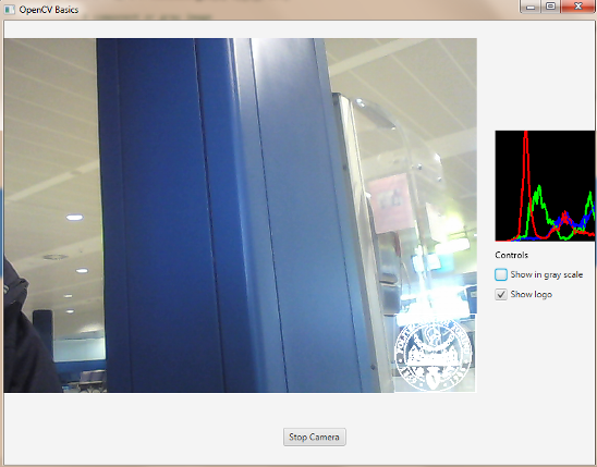
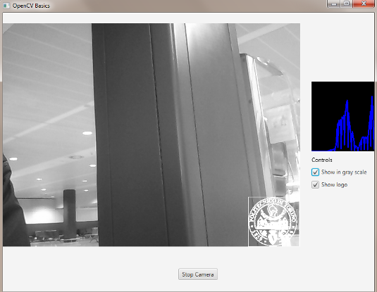
In the RGB case we will need all of the hist defined, in the grayscale case instead we will use just the hist_b one. We are now ready to do the histogram calculation:
RGB 경우 우리는 정의 된 모든 hist를 필요로 할 것이고 그 대신에 우리는 단지 hist_b를 사용할 것입니다. 이제 히스토그램 계산을 할 준비가되었습니다.
where gray is the flag we passed to the showHistogram method.
여기서 gray는 showHistogram 메소드에 전달한 플래그입니다.
Draw the Histogram
Next step is to draw the calculated histogram in our GUI. Open the fxml file with Scene Builder and add an ImageView above the “Controls” text in the right of the BP and set its id:
다음 단계는 GUI에서 계산 된 히스토그램을 그려 보는 것입니다. Scene Builder로 fxml 파일을 열고 BP 오른쪽의 "Controls"텍스트 위에 ImageView를 추가하고 해당 ID를 설정하십시오 :
<ImageView fx:id="histogram" />
Now back to the Controller class. Let’s add a global variable to control the just added image view:
이제 Controller 클래스로 돌아갑니다. 방금 추가 된 이미지보기를 제어하기 위해 전역 변수를 추가합시다.
@FXML
private ImageView histogram;
and continue to write the showHistogram method. First thing first, let’s create an image to display the histogram:
showHistogram 메소드를 계속 작성하십시오. 먼저, 히스토그램을 표시 할 이미지를 만듭니다.
int hist_w = 150;
int hist_h = 150;
int bin_w = (int) Math.round(hist_w / histSize.get(0, 0)[0]);
Mat histImage = new Mat(hist_h, hist_w, CvType.CV_8UC3, new Scalar(0, 0, 0));
before drawing, we first normalize the histogram so its values fall in the range indicated by the parameters entered:
그리기 전에 먼저 히스토그램을 정규화하여 그 값이 입력 된 매개 변수가 나타내는 범위에 속하도록합니다.
Core.normalize(hist_b, hist_b, 0, histImage.rows(), Core.NORM_MINMAX, -1, new Mat());
if (!gray){
   Core.normalize(hist_g, hist_g, 0, histImage.rows(), Core.NORM_MINMAX, -1, new Mat());
   Core.normalize(hist_r, hist_r, 0, histImage.rows(), Core.NORM_MINMAX, -1, new Mat());
}
Now we can draw the histogram in our Mat:
이제 우리는 우리의 매트에 히스토그램을 그릴 수 있습니다 :
for (int i = 1; i < histSize.get(0, 0)[0]; i++){
   Imgproc.line(histImage, new Point(bin_w * (i - 1), hist_h - Math.round(hist_b.get(i - 1, 0)[0])), new Point(bin_w * (i), hist_h - Math.round(hist_b.get(i, 0)[0])), new Scalar(255, 0, 0), 2, 8, 0);
   if (!gray){
      Imgproc.line(histImage, new Point(bin_w * (i - 1), hist_h - Math.round(hist_g.get(i - 1, 0)[0])),new Point(bin_w * (i), hist_h - Math.round(hist_g.get(i, 0)[0])), new Scalar(0, 255, 0), 2, 8, 0);
      Imgproc.line(histImage, new Point(bin_w * (i - 1), hist_h - Math.round(hist_r.get(i - 1, 0)[0])),Math.round(hist_r.get(i, 0)[0])), new Scalar(0, 0, 255), 2, 8, 0);
   }
}
Let’s convert the obtained Mat to an Image with our method mat2Image and update the ImageView with the returned Image:
얻은 Mat를 우리의 method mat2Image로 Image로 변환하고 ImageView를 반환 된 Image로 업데이트합시다 :
histo = mat2Image(histImage);
histogram.setImage(histo);
The source code of the entire tutorial is available on GitHub.
전체 자습서의 소스 코드는 GitHub에서 사용할 수 있습니다.
Next step is to draw the calculated histogram in our GUI. Open the fxml file with Scene Builder and add an ImageView above the “Controls” text in the right of the BP and set its id:
다음 단계는 GUI에서 계산 된 히스토그램을 그려 보는 것입니다. Scene Builder로 fxml 파일을 열고 BP 오른쪽의 "Controls"텍스트 위에 ImageView를 추가하고 해당 ID를 설정하십시오 :
<ImageView fx:id="histogram" />
Now back to the Controller class. Let’s add a global variable to control the just added image view:
이제 Controller 클래스로 돌아갑니다. 방금 추가 된 이미지보기를 제어하기 위해 전역 변수를 추가합시다.
@FXML
private ImageView histogram;
and continue to write the showHistogram method. First thing first, let’s create an image to display the histogram:
showHistogram 메소드를 계속 작성하십시오. 먼저, 히스토그램을 표시 할 이미지를 만듭니다.
int hist_w = 150;
int hist_h = 150;
int bin_w = (int) Math.round(hist_w / histSize.get(0, 0)[0]);
Mat histImage = new Mat(hist_h, hist_w, CvType.CV_8UC3, new Scalar(0, 0, 0));
before drawing, we first normalize the histogram so its values fall in the range indicated by the parameters entered:
그리기 전에 먼저 히스토그램을 정규화하여 그 값이 입력 된 매개 변수가 나타내는 범위에 속하도록합니다.
Core.normalize(hist_b, hist_b, 0, histImage.rows(), Core.NORM_MINMAX, -1, new Mat());
if (!gray){
Core.normalize(hist_g, hist_g, 0, histImage.rows(), Core.NORM_MINMAX, -1, new Mat());
Core.normalize(hist_r, hist_r, 0, histImage.rows(), Core.NORM_MINMAX, -1, new Mat());
}
Now we can draw the histogram in our Mat:
이제 우리는 우리의 매트에 히스토그램을 그릴 수 있습니다 :
for (int i = 1; i < histSize.get(0, 0)[0]; i++){
Imgproc.line(histImage, new Point(bin_w * (i - 1), hist_h - Math.round(hist_b.get(i - 1, 0)[0])), new Point(bin_w * (i), hist_h - Math.round(hist_b.get(i, 0)[0])), new Scalar(255, 0, 0), 2, 8, 0);
if (!gray){
Imgproc.line(histImage, new Point(bin_w * (i - 1), hist_h - Math.round(hist_g.get(i - 1, 0)[0])),new Point(bin_w * (i), hist_h - Math.round(hist_g.get(i, 0)[0])), new Scalar(0, 255, 0), 2, 8, 0);
Imgproc.line(histImage, new Point(bin_w * (i - 1), hist_h - Math.round(hist_r.get(i - 1, 0)[0])),Math.round(hist_r.get(i, 0)[0])), new Scalar(0, 0, 255), 2, 8, 0);
}
}
Let’s convert the obtained Mat to an Image with our method mat2Image and update the ImageView with the returned Image:
얻은 Mat를 우리의 method mat2Image로 Image로 변환하고 ImageView를 반환 된 Image로 업데이트합시다 :
histo = mat2Image(histImage);
histogram.setImage(histo);
The source code of the entire tutorial is available on GitHub.
전체 자습서의 소스 코드는 GitHub에서 사용할 수 있습니다.
카메라 연결을 할 수 없을때 나오는 메시지
Impossible to open the camera connection...
카메라 연결을 열 수 없습니다 ...
집에가서 해봐야겠다.
 Main.java
'DEV' 카테고리의 다른 글
| 6. Face Detection and Tracking (얼굴 인식 및 추적) (0) | 2017.12.09 |
|---|---|
| 5. Fourier Transform (푸리에 변환) (1) | 2017.12.09 |
| 3. Your First JavaFX Application with OpenCV (OpenCV를 사용한 첫 번째 JavaFX 응용 프로그램) (0) | 2017.12.09 |
| 2. Your First Java Application with OpenCV (OpenCV를 사용한 첫 번째 Java 응용 프로그램) (0) | 2017.12.09 |
| 1.Installing OpenCV for Java (java 용 OpenCV 설치) (0) | 2017.12.08 |

